Key Takeaways
- VFDs create adjustable motor output by switching power electronically, which can introduce harmonics and high-frequency noise.
- Grounding, bonding, cable routing, and shielding are often essential first steps.
- Reactors, filters, and isolation equipment must be selected for the actual drive, motor, cable, and load conditions.
- Higher carrier frequency can reduce audible motor noise but may increase losses and heat in the drive.
- Temperature, current, vibration, alarms, and waveform measurements help reveal developing problems.
Variable frequency drives, or VFDs, give facilities precise motor-speed control and can improve process control on fans, pumps, conveyors, and many other loads. They also introduce fast electrical switching that must be managed as part of the complete motor system. A properly selected isolation transformer can be one component of a broader strategy for separating drive-related disturbances from other equipment on the electrical distribution system.
The most reliable approach is not to treat every VFD issue as a drive failure. Motor cable length, grounding, bonding, enclosure layout, carrier-frequency settings, motor construction, and the strength of the incoming electrical system can all affect results. Start by identifying where the disturbance originates and where it is causing stress before selecting mitigation equipment.
Why VFD Systems Can Create Power-Quality Problems
A conventional VFD rectifies incoming AC power to DC, then uses switching devices to create a variable-frequency output for the motor. That process means the input current is not perfectly sinusoidal, while the motor output contains rapid voltage transitions. Input-side harmonics can affect the supply system, whereas motor-side common-mode noise and voltage rise times can affect cables, motors, bearings, and nearby controls.
One small drive on a robust electrical system may have little noticeable effect. A group of drives supplied from the same transformer or feeder can require more careful evaluation, especially when sensitive controls, communications equipment, or other nonlinear loads share the distribution system. Practical variable-speed drive guidance also emphasizes that installation details and application conditions matter when managing performance and interference.
Recognize the Warning Signs
Electrical noise and harmonic stress do not always present as an immediate shutdown. Maintenance teams may instead notice intermittent PLC or sensor faults, unstable instrument readings, communication errors, motor whine at certain speeds, overheating, repeated alarms, or unexplained breaker trips. Premature bearing damage, insulation deterioration, flickering lighting, and interference with adjacent control wiring can also indicate that the motor-drive system needs attention.
Start With a Site Assessment
Measure first, then choose a corrective action. Record the drive and motor ratings, operating speed range, load type, and duty cycle. Check voltage, current, temperatures, alarms, cable length, cable type, shield terminations, and the grounding path between the drive enclosure and motor frame. Identify other loads and sensitive electronics on the same electrical system, then compare the results with the limits and installation guidance supplied by the drive and motor manufacturers.
Improve Grounding, Bonding, and Cable Layout
Build a low-impedance high-frequency path
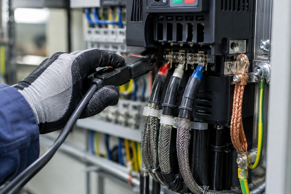
Grounding for personnel protection remains essential, but high-frequency noise control also depends on low-impedance bonding. Bond the drive enclosure, motor frame, cable shield terminations, equipment enclosure, and building grounding system according to the manufacturer’s instructions and applicable electrical requirements. Long, thin grounding conductors can have relatively high impedance at switching frequencies, making them less effective for controlling high-frequency current.
Keep power and signal paths apart
Route motor output cables separately from low-voltage control, instrumentation, and communication wiring whenever possible. If paths must cross, a right-angle crossing generally reduces the length over which noise can couple into the signal conductors. Use cable approved for VFD output service, keep motor leads reasonably short, avoid unnecessary loops, and terminate shields correctly at the drive and motor ends where the system design calls for it.
Choose Harmonic and Noise Controls for the Actual Problem
- Input reactors can limit current changes and add impedance between the drive and supply.
- DC link chokes can reduce certain input-current effects by smoothing current in the drive DC bus.
- Passive harmonic filters are designed to reduce selected harmonic components under defined system conditions.
- Active harmonic filters can respond to changing load conditions and compensate for a broader range of harmonics.
- dV/dt filters reduce the steepness of voltage changes reaching the motor.
- Sine-wave filters provide a more sinusoidal motor voltage waveform and may be appropriate for demanding installations or long motor leads.
- Isolation equipment can support cleaner distribution arrangements and help separate a drive supply from other equipment.
These controls are not interchangeable. A long motor cable may point toward output filtering, while excessive input distortion may require line-side analysis and mitigation. Selecting a device only by motor horsepower or drive rating, without checking voltage, current, system impedance, cable length, and operating conditions, can produce disappointing results.
Match the Design to the Application
Short cable runs, long cable runs, single-drive installations, multi-drive lineups, constant-torque machinery, variable-torque fan and pump loads, regenerative systems, and active-front-end drives have different electrical characteristics. Environmental conditions matter as well. Heat, contamination, humidity, altitude, and enclosure cooling all affect component life and available thermal margin.
Motor selection deserves the same attention as drive selection. Inverter-duty motors are designed for the electrical demands associated with VFD operation, but application details still determine whether added protection is needed. Research into reducing heat and wear in high-power motor-drive systems reflects the continuing importance of managing common-mode voltage, losses, and component stress.
Reduce Motor Heating and Bearing Damage
Fast switching can create high-frequency current paths that may involve motor bearings. Depending on the motor, drive, cable system, and service conditions, shaft grounding devices or insulated bearings may be considered as part of an engineered solution. Review motor temperature, vibration, bearing condition, and lubrication practices during planned maintenance. Also evaluate carrier-frequency changes carefully because a setting that reduces audible noise may raise switching losses and drive temperature.
Use Measurements Instead of Guesswork
A useful test plan includes measuring distortion at the appropriate point in the electrical system, checking voltage and current balance, comparing temperatures at the drive, motor, cables, transformer, and switchgear, and reviewing long-term trends. When waveform issues are suspected, use a suitable power-quality analyzer or oscilloscope with the correct probes and safety procedures. A single reading can be misleading, while trending data across operating conditions helps identify repeatable causes.
Build a Practical Maintenance Plan
Inspect cooling fans, ventilation openings, terminals, cable insulation, shield connections, and enclosure cleanliness. Review fault histories rather than resetting recurring alarms without investigation. Track motor current, temperature, vibration, and unusual noise, particularly after equipment changes. Reassess power quality when adding drives, changing motors, extending cable runs, or modifying the distribution system.
Common Mistakes to Avoid
- Adding filters before confirming the type and location of the problem.
- Running control wiring beside VFD motor leads for long distances.
- Ignoring bonding between the drive, motor, cable shield, and equipment enclosure.
- Using unsuitable cable or poor shield terminations on drive output circuits.
- Changing carrier frequency without reviewing thermal limits.
- Assuming one successful mitigation method will suit every drive installation.
Conclusion
Reliable VFD operation depends on a system-level approach. Measure the installation, improve grounding and cable practices, match harmonic and noise controls to the application, and maintain the drive and motor as connected equipment. That process helps reduce electrical interference, limit motor stress, and support dependable operation over the life of the system.